Our Technologies
Lauris Technologies – Where Innovation Meets Excellence!
At Lauris Technologies, we pride ourselves on staying at the forefront of technological evolution. Our diverse portfolio encompasses a spectrum of solutions tailored to meet the unique needs of industries including gas, flue gas and associated gas measurement.
Ultrasonic Flow Measuring Principle
Lauris flow measurement technology is based on transit-time measurement, a principle which was proven to be far superior in terms of accuracy and rangeability against other methods such as Doppler velocity measurement or cross-correlation method.
Transit-time measurement is the basis of ultrasonic liquid and gas flow meters
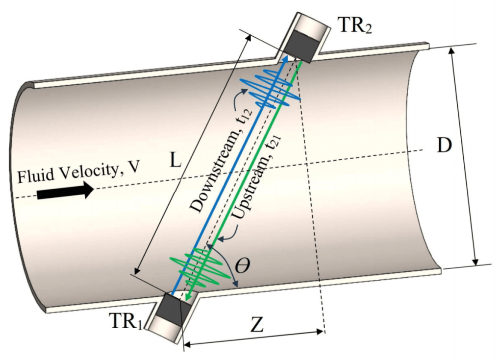
Pulse from transducer 1 (TR1) arrives faster at transducer 2 (TR2) due to fluid velocity V. In contrast, the pulse from TR1 to TR2 is slowed down by the fluid flow. The result is: fluid velocity is proportional to ultrasonic path length (L), the tilt angle (Θ), and time difference t12 and t21, the only parameter which is measured:
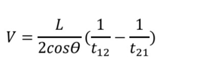
The equation above indicates that measured velocity, V, is not dependent on speed of sound and, therefore, ultrasonic flow measurement is technically not affected by the nature of the fluid, and pressure and/or temperature. As a note, this statement is not exactly correct as the nature of ultrasound propagation in the media is more complex, but it can be effectively applied as a first approximation in most of engineering evaluations. Ultrasonic path is angled to the pipe to get the axial component Z which defines sensitivity of the method. Perpendicular path (Θ=0°,Z=0) provides zero-time difference and, therefore, cannot be used in flow meters. By combining of both timings t12 and t21, the effect of ultrasound acceleration and deacceleration by the fluid motion is compensated and the value of sound speed, C, can be achieved:
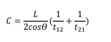
The equation above indicates that measured velocity, V, is not dependent on speed of sound and, therefore, ultrasonic flow measurement is technically not affected by the nature of the fluid, and pressure and/or temperature. As a note, this statement is not exactly correct as the nature of ultrasound propagation in the media is more complex, but it can be effectively applied as a first approximation in most of engineering evaluations. Ultrasonic path is angled to the pipe to get the axial component Z which defines sensitivity of the method. Perpendicular path (Θ=0°,Z=0) provides zero-time difference and, therefore, cannot be used in flow meters. By combining of both timings t12 and t21, the effect of ultrasound acceleration and deacceleration by the fluid motion is compensated and the value of sound speed, C, can be achieved:
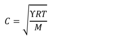
Where Υ is the adiabatic constant, R is the gas constant and T is the absolute temperature of the gas. From the M, the density of gas can be further calculated and, thus, the mass flow can be obtained. However, we must keep in mind that the gas density obtained in such a way is calculated, not measured like it is done with densitometers. The relationship between M and C can vary with the gas content and, therefore, the relationship M=function[C] cannot be used as primarily measurement of gas mass flow. Transducers TR1 and TR2 operate in a sequential mode, each switch from emitting to receiving in every half of the period. Operating frequencies of Lauris transducers are from 50 to 200 kHz. The accuracy of the fluid velocity measurement is formally defined by the accuracy of time measurement between the Start and Stop points.

While the Start point is well defined, the Stop event is not due to several reasons. Electrical noise is generated by electronics and is enhanced by the traveling along long coaxial cables.
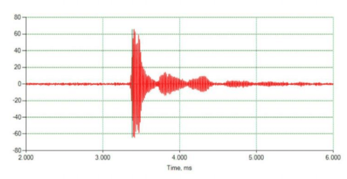
The amplitude of receive signal can be severely reduced by transducer fouling. This effects frequently takes place in flare gas flow measurement where gases are particularly dirty and wet. The receive signal is oscillating because piezoelectric transducers are in ertialelements, and their bandwidth is limited. Also, received ultrasonic pulses are superimposed by properties of both TR1 and TR2 transducers which are close but not identical. Oscillations may cause incorrect detection of the Stop point by catching the wrong maximum of the signal. Ultrasonic paths are not exact straight lines but will change with the high fluid velocity. Local fluctuations of fluids along ultrasonic paths (turbulence) change the time of pulse arrival and, thus, the accuracy of the defining the Stop point. Various techniques are used to mitigate these effects. They include sweeping frequency with further cross-correlation, digital pulse coding, phase measurement, etc. Lauris developed a proprietary algorithm for exact detection of start & stop positions which combines transit-time and transit-phase measurement. All Lauris flow meters are built on classic wetted design where transducers are directly exposed to the moving fluid. This solution is more complex than clamp-on ultrasonic flow measurement. However it is fully paid off by being able to measure flow of practically any liquid or gas from lowest to highest pressures including unprocessed fluids with multiphase constituents.
Sensor Technology
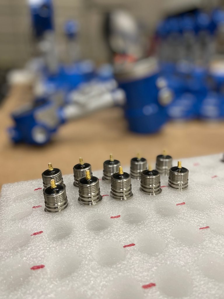
The ultrasonic transducers are a vital part of each Lauris manufactured flow meter. To achieve the highest flow measurement accuracy and the greatest turn down ratio, Lauris Technologies develops and manufactures its own transducers. The use of in-house design and manufacturing of the sensors allows us to precisely dial in the frequency band and signal pulse quality for each pair of transducers. The proprietary sensor technology has taken over a decade of meticulous trial and error iterations to arrive at the correct composition resulting in the industry leading ultrasonic transducers.

Laser and Fiber Optic Measuring Methods
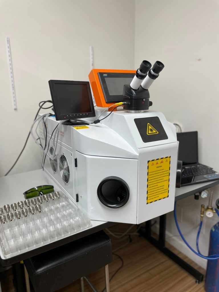
Laser and Fiber Optic Measuring Methods. Many optical and acoustic phenomena are described similarly. Lauris utilizes their optical expertise by offering custom solutions to various challenging applications. This includes but not limited to high temperature, vibrations, aggressive environments, miniature sizing, and others. Lauris in-house optical manufacturing capabilities comprises of laser welding and micro machining, custom fiber optic forming, etc. OEM sensing systems operate from cryogenic temperatures to over 1000°C.
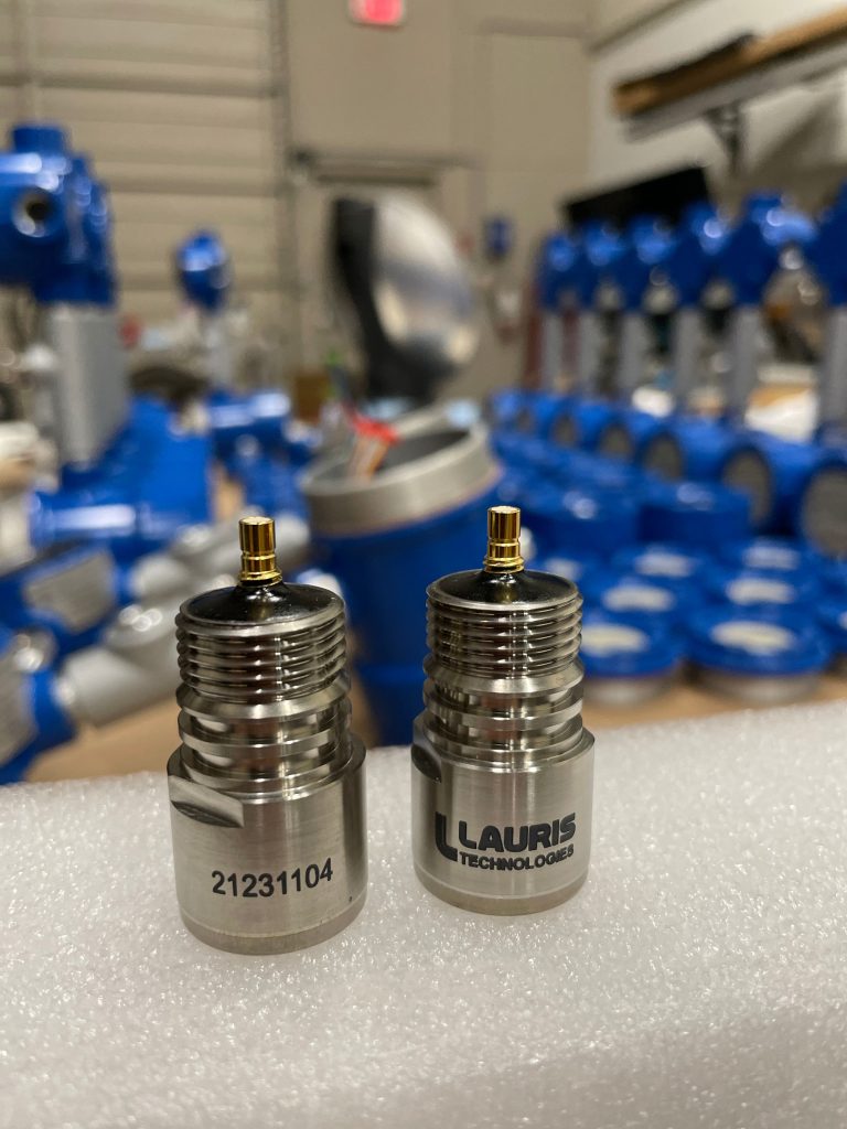
The transducer housing has been rigorously tested in both high pressure and high temperature environments to withstand most demanding applications. Each pair of transducers undergoes initial bench test to assess the pulse quality benchmarked against verified pair as per the ISO program. The cap and the connector are precision laser welded and engraved for traceability.
The quick disconnect design allows for swapping of the transducers with ease, reducing operational downtime. Transducer casing material can be tailored to suit specific design conditions and gas composition. The standard transducers are manufactured from Grade 5 Titanium allowing for maximum corrosion resistance in the most sever of applications. The use of Monel was introduced in 2023 to combat the detrimental effects of high percentage of Methane (CH4). We are also in the final stages of manufacturing our high temperature model, capable of operating temperatures of about 600degC.
The Lauris Advantage:
- Innovation Beyond Boundaries:
What sets Lauris Technologies apart is our unwavering commitment to pushing boundaries. Our passion for innovation drives us to create solutions that not only meet today’s challenges but also anticipate the needs of tomorrow.
- Collaborative Partnerships:
We believe in the power of collaboration. Partner with us to embark on a journey of co-creation, where your unique challenges meet our technological expertise to forge solutions that make a lasting impact.
